
فئات
بلوق جديد
How Can You Calculate The Required CFM For A Plastic Centrifugal Fan Enclosure?
September 21 , 2026When engineers design a plastic enclosure that contains electronic components, motors, power supplies, control boards, sensors, or other heat generating devices, one of the most important questions is how much cooling airflow the enclosure actually needs. Choosing a centrifugal fan only by looking at its maximum airflow rating can easily lead to an undersized or oversized cooling system.
The more practical approach is to calculate the required CFM first, determine the allowable temperature rise, evaluate the airflow resistance inside and outside the enclosure, and then select a centrifugal fan that can deliver the required airflow at the actual system pressure.
For manufacturers and OEM engineers, this process is especially important because a plastic enclosure can have a relatively small internal volume while still producing a significant amount of heat. A compact enclosure may also contain narrow airflow channels, filters, protective grilles, circuit boards, cables and other components that increase resistance.
China Chungfo Fan focuses on the research, development and manufacturing of DC and AC fans, centrifugal blowers, cross flow fans, axial fans, frameless fans and related motor products. For enclosure cooling applications, the fan selection process can be optimized by combining thermal calculations with airflow and static pressure testing.
1,Understanding CFM In A Plastic Fan Enclosure
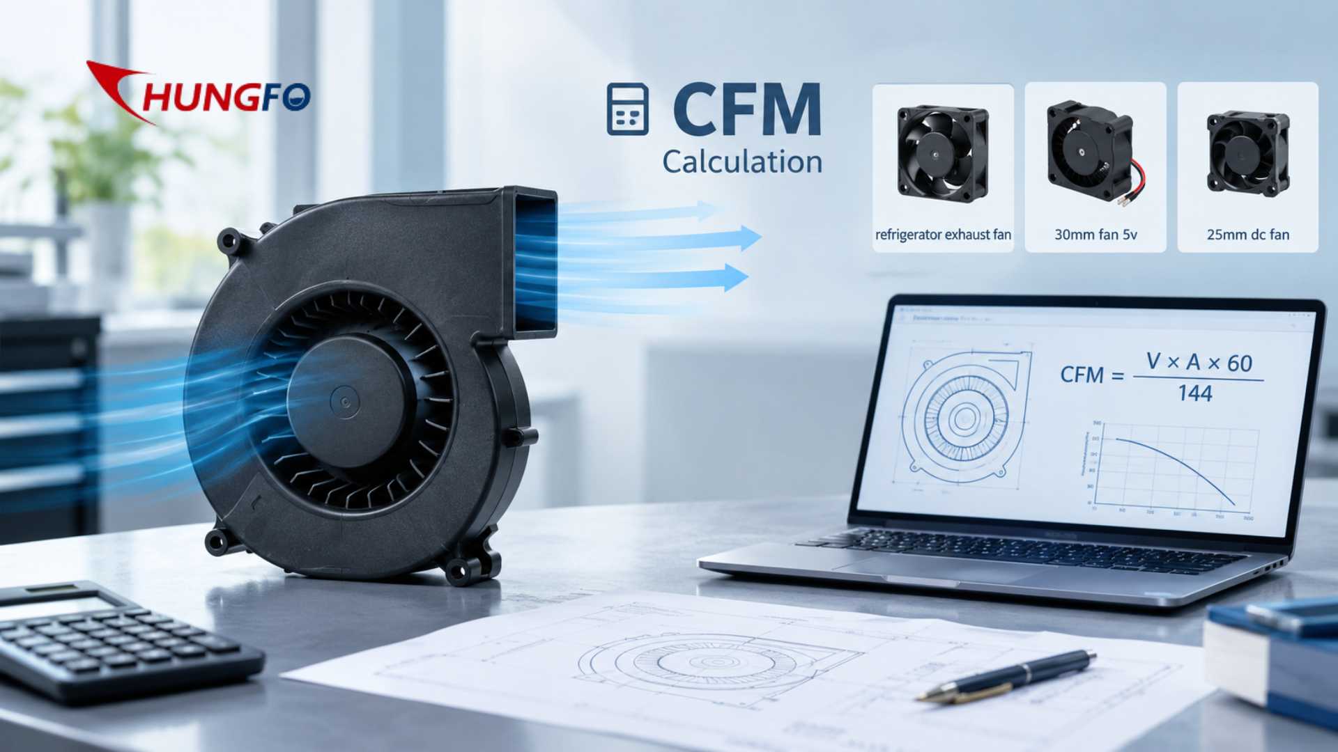
CFM means cubic feet per minute. It describes the volume of air that a fan can move during one minute. In an enclosure cooling application, the required CFM represents the amount of air that must pass through the enclosure to remove the heat generated by the internal components while keeping the internal temperature within the required range.
However, there is an important difference between required airflow and the airflow printed on a fan specification sheet.
A fan may have a free air airflow rating of a certain CFM when there is almost no resistance at the inlet or outlet. Once the same fan is installed inside a plastic enclosure, the real airflow can become significantly lower because the air must pass through vents, filters, grilles, ducts, heat sinks and internal components.
Recent engineering guidance consistently emphasizes that free air airflow should not be treated as the final installed airflow. The actual operating point is determined by the relationship between the fan performance curve and the resistance of the enclosure system.
Therefore, the basic engineering question is not simply “How many CFM does the fan produce?”
The better question is “How many CFM does the enclosure require at the actual static pressure of the system?”
2,Why CFM Is Important For Plastic Enclosures
Plastic enclosures are widely used in household appliances, electronic equipment, control systems, communication equipment, medical devices, industrial machines, charging equipment and small electrical products.
Compared with large metal cabinets, plastic enclosures are often designed to be compact, lightweight and visually integrated with the final product. This makes thermal management more challenging.
A small enclosure can contain several heat producing components. A power supply may generate heat. A motor driver may generate heat. A circuit board may release heat continuously. A transformer, relay, controller or LED module may also contribute to the total thermal load.
If the heat cannot be removed efficiently, the internal temperature will continue to rise.
Excessive temperature can affect component reliability, electrical performance, insulation materials, lubricant life, plastic deformation resistance and the overall service life of the product.
The purpose of the cooling fan is therefore not simply to create airflow. Its purpose is to establish a sufficient air exchange rate so that the heat generated inside the enclosure can be continuously transported away.
3,The Basic Formula For Required CFM
For a first engineering estimate, the most useful heat removal formula is:
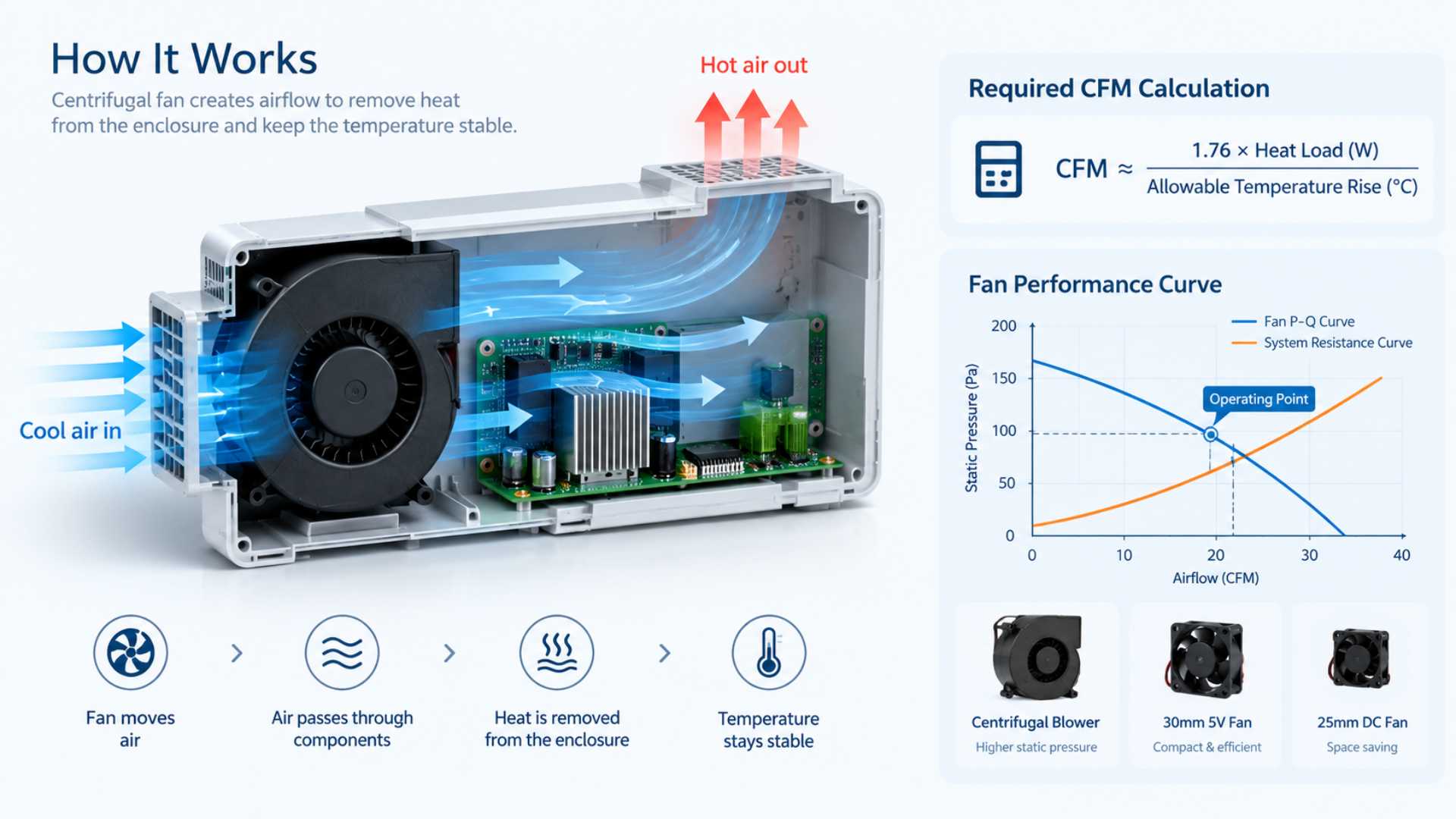
Required CFM ≈ 1.76 × Heat Load W ÷ Allowable Temperature Rise °C
The formula is based on the relationship between heat energy, airflow, air density and the specific heat capacity of air. Recent technical references provide the same approximate relationship for preliminary enclosure cooling calculations.
In this formula, heat load means the amount of heat generated inside the enclosure.
Allowable temperature rise means the maximum acceptable difference between the enclosure inlet air temperature and the internal or outlet air temperature used for the thermal design.
For example, assume an enclosure contains components that generate a total of 100 W of heat.
If the allowable temperature rise is 10°C, the theoretical airflow requirement is:
Required CFM = 1.76 × 100 ÷ 10
Required CFM = 17.6 CFM
This means approximately 17.6 CFM of actual airflow is required under the assumptions of the simplified calculation.
The important word here is “actual.”
A fan advertised as 17.6 CFM in free air is not automatically suitable.
The selected fan must be capable of delivering approximately 17.6 CFM at the static pressure created by the enclosure.
4,How To Calculate The Total Heat Load
Before calculating CFM, the total heat load must be determined.
This is one of the most important steps because the required airflow depends directly on the heat that must be removed.
The heat load should normally include the power dissipated by every major component inside the enclosure.
For example, a plastic control enclosure could contain a power supply that dissipates 30 W, a motor controller that dissipates 20 W, a control PCB that dissipates 15 W, a relay system that dissipates 5 W and other electronic components that dissipate 10 W.
The approximate total heat load would therefore be:
30 W + 20 W + 15 W + 5 W + 10 W = 80 W
The designer should use actual heat dissipation rather than simply adding the rated electrical input power of every component.
A device consuming 100 W of electrical power does not necessarily convert all 100 W into heat inside the enclosure. Some energy may be transferred mechanically, electrically or through another output.
For accurate engineering, the component manufacturer’s loss data, measured temperature data or direct thermal testing should be considered.
Once the total heat load is known, it can be inserted into the airflow formula.
5,How Allowable Temperature Rise Changes CFM
Allowable temperature rise has a major effect on required airflow.
Consider a 100 W heat load.
If the allowable temperature rise is 5°C:
Required CFM = 1.76 × 100 ÷ 5
Required CFM = 35.2 CFM
If the allowable temperature rise is 10°C:
Required CFM = 17.6 CFM
If the allowable temperature rise is 15°C:
Required CFM ≈ 11.7 CFM
If the allowable temperature rise is 20°C:
Required CFM = 8.8 CFM
This demonstrates an important design principle.
The smaller the allowable temperature rise, the greater the required airflow.
If the electronics must remain only 5°C above ambient temperature, considerably more airflow will be required than if a 20°C temperature rise is acceptable.
The allowable temperature rise should therefore come from the actual thermal requirements of the equipment rather than from an arbitrary fan specification.
6,Calculating CFM From Watts
A useful engineering workflow is to begin with watts rather than fan size.
Suppose a plastic enclosure contains:
Power supply heat loss: 40 W
Control board heat loss: 15 W
Motor driver heat loss: 25 W
Other electronic losses: 10 W
Total heat load: 90 W
If the maximum allowable temperature rise is 10°C:
Required CFM = 1.76 × 90 ÷ 10
Required CFM = 15.84 CFM
The preliminary thermal target is therefore approximately 15.8 CFM.
If the design engineer wants to account for practical airflow losses, the selected fan may need to provide a higher catalog airflow than 15.8 CFM, provided that its performance curve shows that approximately 15.8 CFM can still be delivered at the required system pressure.
This is why simply matching the calculated CFM to the free-air rating can produce disappointing results.
7,Considering Plastic Enclosure Volume
Enclosure volume is also relevant, but it should not replace the heat load calculation.
For a rectangular enclosure, volume can be calculated as:
Volume = Length × Width × Height
If the dimensions are measured in feet, the result is cubic feet.
For example, an enclosure measuring 2 ft × 1.5 ft × 1 ft has a volume of:
2 × 1.5 × 1 = 3 cubic feet
The volume tells the designer how much air is contained inside the enclosure, but it does not tell the designer how much heat is being generated.
A small enclosure with 150 W of heat may need more cooling airflow than a much larger enclosure with only 30 W of heat.
For this reason, heat load and allowable temperature rise should normally be the primary variables for thermal airflow calculation.
Volume can then be used as a secondary check for air exchange and internal airflow distribution.
8,Air Changes Per Hour As A Secondary Method
For ventilation applications, another method is to use air changes per hour.
The formula is:
CFM = Enclosure Volume × Air Changes Per Hour ÷ 60
For example, if an enclosure has a volume of 3 cubic feet and the design target is 60 air changes per hour:
CFM = 3 × 60 ÷ 60
CFM = 3 CFM
This calculation can be useful when the objective is general ventilation rather than removing a precisely known electronic heat load.
However, for a heat generating electronic enclosure, the heat load method is generally more informative because it directly connects airflow to the amount of heat that needs to be removed.
Air changes can then be used as a supplementary design check.
9,Why Static Pressure Must Be Included
After calculating the required airflow, the next major question is static pressure.
This is where centrifugal fans can provide a major advantage.
Plastic enclosures often have restricted airflow paths. The inlet may contain a protective grille. A filter may be installed to prevent dust from entering. The outlet may have a narrow opening. Internal circuit boards may block the airflow. A duct may force the air to change direction.
Each restriction produces a pressure drop.
The total system resistance can include inlet resistance, outlet resistance, filter resistance, grille resistance, duct resistance, bends, heat sinks and internal component obstruction.
Recent fan selection references emphasize that the actual operating point is determined by the intersection of the fan performance curve and the system resistance curve.
This means a fan with a higher free-air CFM rating can sometimes perform worse in a restrictive enclosure than a centrifugal fan with a lower free-air rating but stronger pressure capability.
10,Understanding The Fan P-Q Curve
A fan P-Q curve shows the relationship between airflow and static pressure.
At very low resistance, the fan can produce relatively high airflow.
As system resistance increases, airflow decreases.
At maximum static pressure, airflow approaches zero.
The actual operating point occurs where the fan curve intersects the resistance curve of the enclosure.
For example, suppose a centrifugal fan has a free-air airflow rating of 30 CFM.
The enclosure may create 100 Pa of resistance.
If the fan curve shows that the fan can deliver 22 CFM at 100 Pa, then the practical airflow is approximately 22 CFM, not 30 CFM.
If the thermal calculation requires 25 CFM, that fan would not meet the requirement even though its catalog free-air rating appears higher than the calculated value.
This distinction is extremely important when selecting a plastic centrifugal fan.
11,Estimating Enclosure Resistance
The easiest way to improve fan selection accuracy is to identify every restriction in the airflow path.
The intake grille should be evaluated.
The outlet grille should be evaluated.
Filters should be evaluated.
Ducts should be evaluated.
Sharp turns should be evaluated.
Narrow passages should be evaluated.
Heat sinks and densely packed electronic assemblies should be evaluated.
The more restrictive the system becomes, the more static pressure capability the fan needs.
A simple open enclosure may have relatively low resistance.
A compact sealed or semi-sealed plastic enclosure with a filter and narrow exhaust passage may have substantially higher resistance.
In engineering development, prototype testing can provide a more reliable pressure-drop value than theoretical estimation alone.
12,How A Centrifugal Fan Helps In A Compact Enclosure
Centrifugal fans are often selected when air must move through a restrictive path.
Unlike many axial fans that move air mainly along the axis of rotation, centrifugal fans accelerate air radially through an impeller and volute structure.
This makes them useful for applications where the airflow needs to enter through one direction and exit through another direction or where higher static pressure is required.
For example, a plastic electronic enclosure may have an intake opening on one side and an exhaust duct on the opposite side.
The centrifugal fan can be integrated into the enclosure so that air is pulled across the heat generating components and discharged through a narrow outlet.
This arrangement can improve the overall airflow path and help remove heat from specific areas.
13,How To Calculate A Practical Safety Margin
The theoretical CFM calculation is a starting point rather than the final fan specification.
Real systems contain manufacturing tolerances, dust accumulation, filter loading, airflow leakage, component obstruction and changes in environmental conditions.
Therefore, engineers commonly include a design margin.
The appropriate margin depends on the application.
For a preliminary design, an engineering team may decide to use a 20% to 30% airflow margin, but this should be treated as a project design assumption rather than a universal standard.
For example, if the calculated requirement is 20 CFM and a 25% design margin is selected:
20 × 1.25 = 25 CFM
The design target becomes approximately 25 CFM.
However, the final fan must still be able to deliver 25 CFM at the actual operating pressure.
A large free-air CFM number does not compensate for inadequate static pressure.
Example Calculation For A Plastic Centrifugal Fan Enclosure
Consider a plastic enclosure used for electronic equipment.
The internal heat load is 120 W.
The maximum ambient temperature is 35°C.
The maximum desired internal air temperature is 45°C.
Therefore:
Allowable temperature rise = 45°C − 35°C
Allowable temperature rise = 10°C
The preliminary airflow calculation is:
Required CFM = 1.76 × 120 ÷ 10
Required CFM = 21.12 CFM
Now assume the design team applies a 25% engineering margin:
21.12 × 1.25 = 26.4 CFM
The preliminary design target becomes approximately 26.4 CFM.
The engineer then evaluates the enclosure resistance.
Suppose the inlet grille, filter, internal passages and outlet together create a system resistance of 120 Pa at approximately 26 CFM.
The engineer now needs to find a centrifugal fan whose performance curve can deliver at least approximately 26 CFM at 120 Pa.
A fan that produces 35 CFM at zero pressure may not be suitable if it can deliver only 20 CFM at 120 Pa.
Another fan with a free-air rating of 32 CFM could be more suitable if its performance curve provides 28 CFM at 120 Pa.
This example shows why CFM calculation and static pressure evaluation must be performed together.
14,Using Small DC Fans In Compact Enclosures
Not every enclosure requires a large centrifugal blower.
Some compact electronic products have relatively low heat loads and limited installation space.
In these applications, a small DC fan may be sufficient.
A 30mm fan 5v can be considered for compact electronics, portable devices, small control modules and other low-power applications where both physical size and operating voltage are limited.
The same principle applies to a 25mm dc fan. Its small frame size can be useful where the available installation area is extremely limited.
However, the small size of the fan does not remove the need for engineering calculations.
The designer still needs to determine the required airflow, available static pressure, operating voltage, noise requirement, operating temperature and expected lifetime.
For very compact products, the fan may also need to operate continuously for thousands of hours, making motor design, bearing selection and thermal reliability important.
15,Small Fan Versus Centrifugal Fan
The decision between a small axial fan and a centrifugal fan should be based on the airflow path.
If the enclosure has a relatively open airflow path and low resistance, an axial fan may provide an efficient solution.
If the air must travel through a narrow duct, filter or complicated internal path, a centrifugal fan may be more suitable because of its ability to generate higher static pressure.
A 25mm dc fan may be appropriate for a small electronic module with a short and open ventilation path.
A 30mm fan 5v may be suitable for compact consumer electronics where the power supply is limited to 5 V.
A centrifugal blower can become more attractive when the same compact enclosure contains narrow airflow channels or a longer duct.
The correct choice should always be confirmed using the fan performance curve rather than frame size alone.
16,Application Example: Refrigerator Cooling
Refrigeration equipment provides another useful example of enclosure airflow design.
A refrigerator contains compressors, control systems, heat generating electrical components and heat exchange structures.
A refrigerator exhaust fan may be used in certain ventilation arrangements to move warm air away from a designated area.
However, the exact airflow requirement depends on the heat load, available ventilation area, temperature limits, pressure losses and overall refrigeration system design.
The fan should not be selected simply because a refrigerator application appears to require high airflow.
The designer should calculate the heat that must be removed and determine the required operating airflow.
If the airflow must pass through a narrow channel or restricted outlet, static pressure should also be considered.
17,The Importance Of Airflow Direction
A fan can have sufficient CFM on paper and still provide poor cooling if the airflow direction is badly designed.
Air should normally enter through a cooler region and travel across the heat generating components before leaving the enclosure.
If the inlet and outlet are positioned too close together, the fan may circulate air locally without effectively cooling the rest of the enclosure.
This can create an airflow short circuit.
The outlet air may immediately return toward the inlet rather than passing through the main heat generating region.
For compact plastic enclosures, computational fluid dynamics can be used for complex designs, but physical prototype testing remains valuable.
Temperature sensors can be installed near critical components to determine whether the airflow is actually reaching the required locations.
18,Avoiding Hot Spots Inside The Enclosure
The average enclosure temperature does not always represent the temperature of the most sensitive component.
A power transistor, motor controller or voltage regulator may operate at a much higher temperature than the surrounding air.
This is why airflow distribution matters.
A centrifugal fan can be positioned so that airflow is directed toward the region with the highest heat density.
Baffles can also be used to prevent air from bypassing critical components.
The objective is not merely to achieve the calculated CFM at the fan outlet.
The objective is to ensure that the required amount of cooling air reaches the components that actually need cooling.
Considering Ambient Temperature
Ambient temperature must be included in the thermal design.
A system operating in a room at 20°C has a very different cooling requirement from the same system operating at 40°C.
If the maximum internal component temperature is 60°C, the allowable temperature rise at 20°C ambient may be 40°C.
At 40°C ambient, the allowable temperature rise is only 20°C.
The second condition requires significantly more airflow.
This is one reason why industrial and outdoor equipment often requires more careful fan selection than consumer equipment used in controlled indoor environments.
19,Altitude And Air Density
Air density changes with altitude and temperature.
At higher altitude, air becomes less dense.
For the same volumetric airflow, the mass of air moving through the enclosure can therefore be lower.
The basic CFM formula assumes approximately standard air conditions, so high-altitude applications may require additional engineering correction.
This is particularly relevant for equipment intended to operate in mountainous regions or in applications where the environmental conditions vary significantly.
For preliminary calculations, the standard formula is useful.
For critical equipment, the actual operating temperature, altitude and air density should be included in the thermal calculation. Engineering references also recommend correcting airflow calculations when environmental conditions materially differ from standard assumptions.
Fan Voltage And Control Requirements
Once airflow and pressure requirements are known, the electrical specification must also be matched.
Common DC fan voltages include 5 V, 12 V and 24 V.
A compact product may require a 5 V fan because the main electronic system already operates at 5 V.
Industrial equipment may use a 12 V or 24 V fan depending on the available power architecture.
In addition to voltage, engineers should consider current, startup behavior, locked rotor protection, speed control, tachometer output, PWM control and alarm functions where required.
A fan that meets the airflow requirement but cannot integrate correctly with the product's power and control system is not a complete solution.
20,Noise Considerations
Noise can become an important factor in small plastic enclosures.
A fan with a higher rotational speed can provide strong airflow but may also generate more aerodynamic and motor noise.
In household appliances, medical equipment, office electronics and consumer products, acoustic performance may be nearly as important as thermal performance.
The designer should therefore avoid simply choosing the highest RPM fan available.
A better approach is to identify the required operating point and select a fan that can deliver the necessary airflow and pressure without excessive speed.
The airflow path itself should also be designed carefully because turbulence, sharp bends and narrow openings can generate additional noise.
Reliability And Continuous Operation
For equipment designed for continuous operation, fan reliability is an important consideration.
The fan may run for many hours every day.
Bearing selection, motor design, winding temperature, operating temperature, vibration and dust exposure can all influence service life.
For this reason, China Chungfo Fan considers not only airflow but also product construction, electrical characteristics and application conditions when developing fan solutions.
For OEM customers, customization may include voltage, current, speed, airflow, pressure, wire configuration, connector configuration and other functional requirements.
21,Testing The Final Enclosure
Theoretical calculations should always be by prototype testing when the application is important.
A prototype enclosure can be tested under representative ambient conditions.
Temperature sensors can be placed near critical components.
The fan can then be operated at the intended voltage and control condition.
Engineers can measure inlet temperature, outlet temperature, internal hot spot temperature, airflow and pressure.
The measured results can then be compared with the original calculation.
If the internal temperature is too high, several factors should be investigated.
The fan may not be producing enough airflow at the actual system pressure.
The airflow path may be blocked.
The inlet or outlet may be too small.
The fan may be positioned incorrectly.
There may be excessive leakage.
The heat load may be higher than originally estimated.
The enclosure may also have insufficient ventilation area.
Testing allows these issues to be identified before mass production.
22,Common Mistakes When Calculating CFM
One common mistake is selecting a fan based only on the maximum CFM printed on the datasheet.
This ignores static pressure.
Another mistake is calculating airflow based only on enclosure volume.
Volume alone does not describe how much heat must be removed.
A third mistake is using the rated electrical power of every component as its heat load without determining actual power dissipation.
Another problem is using an excessively small temperature rise without considering whether the required airflow is physically achievable.
Designers sometimes also forget that filters become more restrictive as dust accumulates.
The airflow system should therefore be evaluated under realistic operating conditions.
Another common mistake is placing the inlet and outlet too close together.
This can result in air recirculation rather than effective cooling.
A final mistake is selecting a fan before defining the thermal requirements.
The better sequence is to calculate the heat load, determine the allowable temperature rise, calculate the required airflow, estimate the system resistance, identify the operating point and then select the fan.
23,A Practical Fan Selection Workflow
The complete process can be summarized as a practical engineering workflow.
First, determine the maximum ambient temperature.
Second, determine the maximum acceptable internal or component temperature.
Third, calculate the allowable temperature rise.
Fourth, calculate the total internal heat load.
Fifth, calculate the theoretical required CFM.
Sixth, evaluate the enclosure airflow path.
Seventh, estimate or measure system static pressure.
Eighth, add an appropriate engineering margin.
Ninth, compare the target operating point with centrifugal fan performance curves.
Tenth, verify the final selection through prototype testing.
This workflow helps prevent the common problem of selecting a fan based on a single catalog number.
24,How China Chungfo Fan Can Support Enclosure Cooling
China Chungfo Fan develops and manufactures a range of DC and AC cooling fan products for different equipment applications.
Its product range includes axial fans, centrifugal blowers, cross flow fans, frameless fans and related motor solutions.
For OEM applications, the fan can be evaluated according to required voltage, current, speed, airflow, static pressure, dimensions, noise, operating environment and wiring requirements.
For compact plastic enclosures, the design process can begin with the customer's heat load and available installation space.
The required CFM can then be calculated and matched with the pressure requirement.
This approach is more reliable than simply selecting a fan according to its external dimensions.
China Chungfo Fan also has production and testing capabilities covering product development, mold development, injection molding, SMT, assembly and quality control.
Testing equipment can be used to evaluate airflow, pressure, noise, electrical performance and other product characteristics.
For OEM and customized applications, these capabilities can help connect the theoretical fan calculation with the actual manufactured product.
25,Conclusion
Calculating the required CFM for a plastic centrifugal fan enclosure begins with heat, not fan size.
The basic preliminary formula is:
Required CFM ≈ 1.76 × Heat Load W ÷ Allowable Temperature Rise °C
This calculation establishes the theoretical airflow requirement.
However, it does not represent the final fan selection.
The designer must also consider static pressure, filters, grilles, ducts, internal components, airflow direction, temperature distribution, ambient temperature, altitude, noise and reliability.
The most important distinction is between free-air airflow and actual operating airflow.
A centrifugal fan should be selected according to the point where its performance curve intersects the enclosure system resistance curve.
For a low-resistance enclosure, a compact axial fan may be sufficient.
For a compact enclosure with narrow passages, filters or ducts, a centrifugal fan may provide a more appropriate pressure-flow performance.
Small products may use a 30mm fan 5v or a 25mm dc fan when the heat load and airflow requirements are relatively low, while larger or more restrictive systems may require a higher-performance centrifugal blower.
The same calculation principle can also be applied to applications such as refrigerator exhaust fan systems, electronic cabinets, household appliances, medical equipment, charging equipment and industrial machinery.
The most reliable approach is therefore to calculate the heat load, determine the allowable temperature rise, calculate CFM, evaluate static pressure, select the fan from its performance curve and then verify the final design through testing.
26,FAQ
FAQ 1: What is the basic formula for calculating required CFM?
The preliminary formula is Required CFM ≈ 1.76 × Heat Load in Watts ÷ Allowable Temperature Rise in °C. The result represents the approximate actual airflow required for heat removal under the assumptions of the calculation.
FAQ 2: Is fan free-air CFM the same as actual enclosure airflow?
No. Free-air CFM is normally measured under conditions with very low airflow resistance. Once the fan is installed in an enclosure with filters, grilles, ducts or narrow passages, the actual airflow can decrease. The fan performance curve should therefore be checked at the expected static pressure.
FAQ 3: How much CFM does a 100 W enclosure require?
The answer depends on the allowable temperature rise. At a 5°C temperature rise, the preliminary requirement is about 35.2 CFM. At 10°C, it is about 17.6 CFM. At 15°C, it is about 11.7 CFM. At 20°C, it is about 8.8 CFM.
FAQ 4: Why should static pressure be considered when selecting a centrifugal fan?
Static pressure represents the resistance that the fan must overcome. Filters, grilles, ducts, heat sinks and narrow airflow channels can significantly reduce airflow. A centrifugal fan should therefore be evaluated at the actual pressure requirement rather than only at free-air conditions.
FAQ 5: Can a small DC fan be used for a plastic enclosure?
Yes, if the heat load and airflow requirement are sufficiently low. A 30mm fan 5v or a 25mm dc fan may be suitable for compact electronic products, but the required airflow, static pressure, voltage, noise and operating lifetime must all be evaluated.
FAQ 6: When should a centrifugal fan be selected instead of an axial fan?
A centrifugal fan can be particularly useful when the airflow must pass through a restrictive path, narrow duct, filter or compact internal channel. If the airflow path is relatively open and resistance is low, an axial fan may also be appropriate.
FAQ 7: Does a larger enclosure always need more CFM?
No. Enclosure volume is only one factor. The required airflow is primarily related to the heat load and allowable temperature rise. A small enclosure with a high heat load can require more cooling airflow than a large enclosure with a low heat load.
FAQ 8: Should an airflow safety margin be added?
A design margin can be useful to account for practical factors such as airflow losses, component tolerances, filter loading and operating conditions. The appropriate margin depends on the application and should not be treated as a universal fixed value.
FAQ 9: How can the final fan selection be verified?
The best approach is to compare the required airflow and static pressure with the fan P-Q performance curve and then verify the selected fan in a representative prototype enclosure. Temperature, airflow and pressure can be measured during testing.
FAQ 10: Can China Chungfo Fan provide customized centrifugal fan solutions?
China Chungfo Fan can evaluate fan requirements based on dimensions, voltage, current, speed, airflow, pressure, noise, wiring and application conditions. For OEM projects, these requirements can be used as the starting point for selecting or developing a suitable fan solution.