
فئات
بلوق جديد
ما الذي يسبب تذبذب التدفق في المنافيخ الطاردة المركزية الصغيرة وكيف يمكن للمهندسين منع تدفق الهواء غير المستقر؟
August 31 , 2026تُستخدم المراوح الطاردة المركزية الصغيرة على نطاق واسع في المعدات الإلكترونية، والأجهزة الطبية، والأجهزة المنزلية، وأنظمة التبريد، ومعدات البطاريات، ومعدات الشحن، وخزائن التحكم، وأنظمة التهوية، وغيرها من التطبيقات الصغيرة. ونظرًا لأن هذه المراوح غالبًا ما تُركّب في مساحات محدودة، يحتاج المهندسون عادةً إلى تحقيق التوازن بين تدفق الهواء، والضغط الساكن، والضوضاء، واستهلاك الطاقة، والأبعاد، والموثوقية.
في كثير من التطبيقات، يبدو اختيار منفاخ صغير أمرًا بسيطًا. إذ يمكن للمهندس مقارنة تدفق الهواء المطلوب مع أقصى تدفق هواء مُدرج في ورقة مواصفات المنتج، واختيار طراز ذي سعة كافية. مع ذلك، قد يختلف أداء تدفق الهواء الفعلي اختلافًا كبيرًا بعد تركيب المنفاخ داخل نظام المعدات المتكامل.
والسبب بسيط: المنفاخ لا يعمل بشكل مستقل.
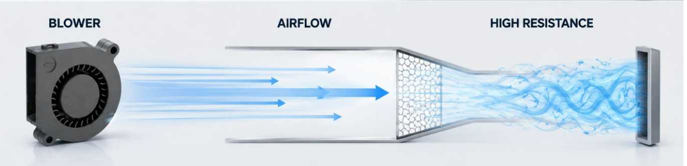
يجب على المروحة التغلب على المقاومة الناتجة عن قنوات الهواء، والمرشحات، ومشتتات الحرارة، وفتحات التهوية، والشبكات، والانحناءات، والممرات الضيقة، والمبادلات الحرارية، وغيرها من المكونات. عندما تزداد هذه المقاومة بشكل كبير، تنحرف نقطة تشغيل المروحة عن نطاقها الأمثل. وقد ينخفض تدفق الهواء بشكل ملحوظ، وقد يتذبذب الضغط، وقد تظهر ضوضاء أو اهتزازات غير معتادة.
في بعض الظروف، يمكن أن يؤدي التفاعل بين المنفاخ ونظام تدفق الهواء المتصل به إلى حالة تشغيل غير مستقرة توصف عادةً بأنها اندفاع المنفاخ أو عدم استقرار التدفق.
بالنسبة للآلات الطاردة المركزية الصناعية الكبيرة، قد يُمثل التذبذب المفاجئ ظاهرة ديناميكية هوائية خطيرة تتضمن تذبذبات قوية في الضغط والتدفق. أما بالنسبة للمراوح الطاردة المركزية الصغيرة المستخدمة في المعدات المدمجة، فغالباً ما يكون الوضع أقل حدة. يُرجح أن يواجه المهندسون مقاومة عالية للنظام، وانخفاضاً ملحوظاً في تدفق الهواء، وتقلبات في الضغط، وضوضاء نابضة، أو عدم استقرار في تدفق الهواء قبل أن يواجهوا سلوك التذبذب المفاجئ الحاد المرتبط بالأنظمة الصناعية الكبيرة.
يُعد فهم هذا التمييز أمراً مهماً عند تصميم المعدات المزودة بمنافخ صغيرة.
تشرح هذه المقالة معنى تذبذب المنفاخ في سياق المنافيخ الطاردة المركزية الصغيرة، ولماذا يمكن أن تتسبب مقاومة النظام المفرطة في تدفق هواء غير مستقر، وكيف يمكن للمهندسين تحديد المشاكل المحتملة، وكيف يمكن للاختيار الصحيح للمنفاخ وتصميم مسار تدفق الهواء أن يقلل من المخاطر.
ما سبب ارتفاع درجة حرارة المروحة؟
يشير مصطلح "تذبذب المنفاخ" إلى حالة ديناميكية هوائية غير مستقرة يتذبذب فيها تدفق الهواء والضغط الناتج عن المنفاخ بدلاً من أن يظل مستقرًا نسبيًا.
ترتبط هذه الظاهرة ارتباطًا وثيقًا بالعلاقة بين أداء المنفاخ ومقاومة النظام.
لكل منفاخ طرد مركزي منحنى أداء. يوضح هذا المنحنى عادةً كيفية تغير تدفق الهواء بتغير الضغط الساكن. عند مقاومة منخفضة للنظام، يستطيع المنفاخ عادةً توفير تدفق هواء مرتفع نسبيًا. ومع ازدياد مقاومة النظام، ينخفض تدفق الهواء بينما يعمل المنفاخ عند ضغط أعلى.
كما أن لنظام المعدات الكامل خصائص مقاومة خاصة به.
على سبيل المثال، تخيل منفاخًا صغيرًا مثبتًا داخل جهاز إلكتروني. يدخل الهواء من خلال شبكة مدخل، ويمر عبر المنفاخ، وينتقل عبر قناة داخلية ضيقة، ويمر عبر مشتت حراري، ويخرج من خلال فتحة تهوية صغيرة.
كل جزء يُحدث مقاومة.
إذا كان مسار تدفق الهواء مفتوحًا نسبيًا، فيمكن للمروحة أن تعمل عند نقطة مستقرة مع تدفق هواء معقول.
إذا أصبح المخرج مسدودًا، فإن مقاومة النظام تزداد.
إذا اتسخ المرشح، تزداد المقاومة مرة أخرى.
إذا تلوث المشتت الحراري بالغبار، فقد تزداد المقاومة بشكل أكبر.
في النهاية، قد يُجبر المنفاخ على التوجه نحو جزء من نطاق تشغيله حيث يصبح تدفق الهواء منخفضًا للغاية ويصبح السلوك الديناميكي الهوائي أقل استقرارًا.
اعتمادًا على تصميم المنفاخ وتكوين النظام، قد يؤدي ذلك إلى نبضات في تدفق الهواء، وتقلبات في الضغط، وتغيرات في الضوضاء، واهتزازات، أو سلوك غير مستقر آخر.
لذلك، لا ينبغي للمهندسين أن ينظروا إلى تذبذب المنفاخ على أنه مجرد مشكلة داخل محرك المنفاخ.
عادة ما يكون ذلك نتيجة للتفاعل بين المنفاخ ونظام تدفق الهواء بأكمله.
هل ظاهرة التذبذب في قوة المروحة شائعة في المراوح الصغيرة؟
هذا سؤال مهم لمصممي المعدات.
قد تعاني المنفاخات الطاردة المركزية الصغيرة من عدم الاستقرار الديناميكي الهوائي، ولكن يجب على المهندسين توخي الحذر عند تطبيق مصطلح "التذبذب" على تطبيقات المنفاخات المدمجة.
قد تتعرض ضواغط الطرد المركزي الصناعية الكبيرة ومراوح النفخ الكبيرة المستخدمة في العمليات الصناعية لظروف اندفاع قوية تتضمن انعكاسًا كبيرًا في التدفق وتذبذبات في الضغط. أما مراوح النفخ الصغيرة التي تعمل بالتيار المستمر والمستخدمة لتبريد الإلكترونيات أو الأجهزة المنزلية، فتعمل عمومًا بمعدلات تدفق أقل بكثير وأحجام أنظمة أصغر.
ونتيجة لذلك، غالباً ما تكون الأعراض مختلفة.
قد يواجه منفاخ صغير ما يلي:
انخفاض تدفق الهواء
ضغط ثابت أعلى
تدفق هواء نابض
تغير الضوضاء الديناميكية الهوائية
زيادة الاهتزاز
حمل المحرك المتذبذب
انخفاض أداء التبريد
قد تكون هذه الظروف ناجمة عن مقاومة النظام المفرطة حتى عندما لا تمثل ارتفاعًا حادًا بالمعنى الصناعي الكلاسيكي.
لذلك، من الأدق بالنسبة للتسويق والتواصل الهندسي أن نشرح أن المنفاخات الطاردة المركزية الصغيرة يمكن أن تواجه تدفق هواء غير مستقر أو سلوكًا يشبه الاندفاع في ظل ظروف النظام غير المواتية.
هذا التمييز يجعل النقاش التقني أكثر مصداقية.
كما أنه يساعد العملاء على فهم أن اختيار منفاخ الهواء لا يتعلق فقط بإيجاد منتج ذي أعلى معدل لتدفق الهواء.
لماذا تُعدّ مقاومة النظام مهمة للغاية
تُعد مقاومة النظام أحد أهم العوامل التي تؤثر على الأداء الحقيقي لمنفاخ طرد مركزي صغير.
قد تتضمن مواصفات المنفاخ قيمة قصوى لتدفق الهواء. ومع ذلك، يُقاس تدفق الهواء الأقصى عادةً في ظل ظروف اختبار محددة، وقد يحدث ذلك عندما يواجه المنفاخ مقاومة ضئيلة للغاية.
المعدات الحقيقية مختلفة.
بمجرد تركيب المنفاخ، يجب أن يمر الهواء عبر مسار تدفق الهواء بالكامل.
يُحدث المرشح مقاومة.
تُحدث الشبكة مقاومة.
يُحدث المشتت الحراري مقاومة.
يؤدي ضيق القناة إلى حدوث مقاومة.
تُسبب القناة الطويلة مقاومة.
يُحدث الانحناء الحاد مقاومة.
يُحدث المخرج الصغير مقاومة.
قد يكون التأثير المشترك كبيراً.
لهذا السبب، ينبغي على المهندسين النظر في العلاقة بين تدفق الهواء والضغط الساكن بدلاً من النظر في أقصى تدفق للهواء وحده.
على سبيل المثال، قد يوفر منفاخ الهواء الذي يتم الإعلان عنه بتدفق هواء حر عالي تدفق هواء أقل بكثير عند توصيله بهيكل تبريد كثيف.
يُعد هذا الأمر بالغ الأهمية في المعدات المدمجة لأن المصممين غالباً ما يكون لديهم مساحة محدودة لممرات الهواء.
عندما يصبح مسار تدفق الهواء المتاح أصغر، يمكن أن يزداد انخفاض الضغط بسرعة.
إذا أصبحت مقاومة النظام عالية جدًا، فقد يقضي المنفاخ معظم وقت تشغيله عند نقطة ذات تدفق هواء منخفض وضغط عالٍ.
قد يؤدي ذلك إلى تقليل أداء التبريد وقد يخلق سلوكًا ديناميكيًا هوائيًا غير مستقر.
الفرق بين تدفق الهواء الحر وتدفق التشغيل الفعلي
من أكثر الأخطاء شيوعاً في اختيار المنفاخ هو مقارنة قيم تدفق الهواء الحر فقط.
يصف تدفق الهواء الحر حالة ذات مقاومة خارجية ضئيلة.
نادراً ما تعمل المعدات الفعلية في ظل ظروف غير مقيدة تماماً.
لنفترض تطبيق تبريد يتم فيه استخدام منفاخ لدفع الهواء عبر مشتت حراري.
إذا كانت زعانف المشتت الحراري متقاربة، فقد تكون مقاومة تدفق الهواء كبيرة.
والآن أضف فلتر الغبار.
ثم أضف مخرجًا ضيقًا.
ثم أضف انحناءين في قناة الهواء.
قد تكون مقاومة النظام النهائية أعلى بكثير مما أشارت إليه الحسابات الأصلية.
يجب على المنفاخ التغلب على كل هذه الخسائر في الضغط.
وبالتالي، يمكن أن يكون تدفق الهواء الفعلي أقل بكثير من الرقم الموضح في ظروف الهواء الحر.
لهذا السبب، يجب أن يأخذ اختيار المنفاخ الاحترافي في الاعتبار دائمًا ضغط النظام المتوقع.
ما الذي يسبب عدم استقرار تدفق الهواء في المنفاخات الطاردة المركزية الصغيرة؟
هناك عدة عوامل يمكن أن تساهم في عدم استقرار تدفق الهواء.
أولها التقييد المفرط للمنافذ الكهربائية.
إذا كانت فتحة المخرج صغيرة جدًا، فيجب على المنفاخ توليد ضغط أعلى لتحريك الهواء عبر النظام.
أما الثاني فهو قناة هوائية صغيرة الحجم.
يؤدي الممر الضيق إلى زيادة سرعة الهواء وفقدان الضغط.
أما الثالث فهو مقاومة المرشح المفرطة.
تصبح المرشحات أكثر تقييداً عندما يتراكم الغبار.
أما السبب الرابع فهو سوء تصميم المدخل.
A blower needs a suitable air supply. If the inlet is partially blocked or airflow enters the impeller unevenly, aerodynamic performance may deteriorate.
The fifth is excessive duct bending.
Sharp bends close to the blower can create turbulence and uneven velocity distribution.
The sixth is improper blower selection.
A blower that is too small may not have sufficient pressure capability for the application.
A blower that is too large may create excessive pressure and force the system to use restrictive control methods.
The seventh is changing operating conditions.
A system may work well during initial testing but become less stable after filters become dirty or when equipment configuration changes.
Why Small Blower Size Does Not Mean Simple Airflow Design
Because small blowers occupy very little physical space, designers sometimes assume that airflow design is also simple.
In reality, compact systems can be more challenging.
A large industrial ventilation system may have sufficient space for smooth ducts, gradual transitions, large filters, and appropriately sized outlets.
A compact electronic device may have only a few centimeters of available space.
The designer may need to route air around circuit boards, heat sinks, batteries, cables, brackets, and structural components.
This creates many local restrictions.
A blower may have excellent performance when tested alone, but the same blower can perform very differently after installation.
Therefore, compact blower applications require careful attention to the complete airflow path.
How To Recognize Potential Blower Instability
Engineers and maintenance personnel can look for several warning signs.
The first is unusual airflow fluctuation.
If the equipment operates under a stable thermal load but airflow repeatedly changes, the airflow path should be inspected.
The second is pressure fluctuation.
A pressure sensor can help identify changes in system pressure that may not be obvious from airflow measurements alone.
The third is unusual noise.
A small blower operating normally should produce relatively consistent aerodynamic noise. Pulsating or changing noise can indicate turbulence, excessive restriction, or unstable airflow.
The fourth is increased vibration.
Aerodynamic instability can create changing forces on the impeller and housing.
The fifth is reduced cooling performance.
If electronic components become hotter even though blower speed has not changed, system resistance or airflow restriction may have increased.
The sixth is changing motor current.
Changes in aerodynamic loading can affect the electrical load of the motor.
These symptoms should be evaluated together rather than individually.
Does Higher RPM Always Solve The Problem?
Increasing blower speed can increase airflow and pressure, but it should not automatically be treated as the solution.
Suppose a filter is becoming blocked.
The equipment begins to experience reduced airflow.
An operator increases blower speed.
Airflow improves temporarily.
However, the filter remains blocked.
The blower now operates at a higher speed and may consume more power while generating higher pressure.
If the system resistance continues increasing, the operating condition may eventually become unfavorable again.
Therefore, higher speed can compensate for some operating changes, but it cannot replace proper airflow-path design and maintenance.
Engineers should always determine why airflow is declining before simply increasing speed.
Selecting The Right Blower Performance
For small centrifugal blowers, the most important selection information includes airflow, static pressure, operating voltage, speed, noise, dimensions, power consumption, operating temperature, and expected service life.
Among these parameters, the airflow-pressure relationship is particularly important.
The required operating point should be identified first.
For example, if the equipment requires a certain airflow while overcoming a defined static pressure, the selected blower should be able to provide that combination under the actual operating conditions.
This is much more meaningful than selecting a blower simply because its maximum airflow is higher than the required value.
Engineers should also consider the operating range.
If the equipment can experience changes in filter condition, temperature, valve position, or airflow demand, the blower should maintain acceptable performance across those conditions.
40mm Blower FanApplications And Airflow Stability
A 40mm blower fan is typically associated with compact equipment where installation space is limited.
Such small blowers can be useful for localized cooling inside electronic devices, control systems, instruments, communication equipment, and other compact assemblies.
However, their small size means that the airflow path can have a relatively large influence on total system resistance.
A small outlet that appears acceptable visually may represent a significant restriction relative to the blower's available airflow area.
Likewise, a narrow internal channel may consume a large portion of the available pressure.
Therefore, when designing a system around a 40mm blower fan, engineers should evaluate the complete airflow path rather than only the blower itself.
The inlet area, outlet area, duct length, bends, filters, and heat dissipation components should all be considered.
100mm Blower FanApplications
A 100mm blower fan provides more installation flexibility than extremely compact blowers in some applications and may be selected when greater airflow or pressure capability is required.
However, larger physical size does not automatically eliminate airflow instability.
A 100mm blower fan can still operate under excessive system resistance if the connected duct, filter, heat exchanger, or outlet is improperly designed.
The same selection principle therefore applies.
Engineers should match the blower to the actual system operating point.
The objective is stable airflow rather than simply maximum airflow.
Blower 5015And Compact Cooling Design
A blower 5015 is an example of the type of compact blower format that can be considered for space-constrained cooling applications.
When using compact blowers of this type, designers should pay particular attention to the relationship between blower dimensions and airflow-path dimensions.
A compact blower may fit easily into the equipment, but the surrounding structure can still restrict airflow.
For example, placing the blower directly against a narrow wall or mounting bracket may reduce the effective inlet area.
Similarly, connecting the outlet to a narrow passage may increase pressure loss.
These details can influence actual performance more than the nominal blower dimensions suggest.
How Inlet Design Affects Blower Performance
The blower inlet is often overlooked.
Air should be able to enter the blower smoothly and reasonably uniformly.
If the inlet opening is partially blocked, the blower may have to operate with an uneven velocity distribution.
A sharp bend immediately before the inlet can also create turbulence.
In compact equipment, engineers may need to position the blower close to other components because of space limitations.
However, leaving adequate inlet clearance can improve airflow quality.
The inlet grille should also provide sufficient open area.
A decorative grille may look attractive but create unnecessary pressure loss if its open area is too small.
How Outlet Design Affects System Resistance
The outlet is equally important.
A blower may generate sufficient pressure, but if the outlet cannot pass the required airflow, system resistance will increase.
The outlet should be appropriately sized.
Sudden contractions should be avoided where possible.
Sharp changes in direction should be minimized.
If a protective grille is required, its open area should be evaluated.
If a filter is installed at the outlet, its pressure drop should be included in the system calculation.
These small design decisions can have a significant effect on the final operating point.
Filters And Their Impact On Blower Operation
Filters are important for protecting equipment from dust, but they inevitably create pressure loss.
A new filter may have relatively low resistance.
After extended operation, dust accumulation can increase pressure drop.
This means the blower operating point can gradually change over time.
A cooling system that performed well during initial testing may therefore deliver less airflow several months later.
For equipment requiring stable thermal performance, filter condition should be included in the maintenance plan.
Engineers should also specify the acceptable filter pressure drop rather than treating filtration as an isolated component.
Heat Sinks Can Also Create Significant Resistance
Heat sinks are widely used in electronic cooling systems.
While a heat sink improves heat transfer, closely spaced fins can restrict airflow.
If the blower must force air through a dense fin structure, static pressure requirements increase.
The thermal engineer should therefore consider both heat transfer and pressure loss.
A heat sink with extremely dense fins may provide a large heat transfer surface but require more blower pressure.
A slightly different fin spacing may reduce pressure loss while still providing adequate thermal performance.
The best solution is usually a balance between thermal performance and airflow resistance.
The Importance Of System Testing
Calculations are important, but prototype testing is often necessary.
A small blower should ideally be tested inside the actual or representative equipment.
Testing should measure airflow, pressure, temperature, noise, vibration, and motor electrical parameters where appropriate.
The equipment should be tested under different thermal loads.
Minimum, normal, and maximum operating conditions should be evaluated.
If the system uses a filter, test both clean and representative loaded conditions when practical.
If the blower uses speed control, the complete control range should also be tested.
This approach allows engineers to identify problems before mass production.
How Engineers Can Reduce Surge Risk
The first step is to reduce unnecessary system resistance.
Use appropriately sized airflow channels.
Avoid unnecessary bends.
Provide adequate inlet and outlet areas.
Select filters with suitable pressure-drop characteristics.
Avoid excessive restrictions around heat sinks.
Choose the blower based on the actual airflow-pressure requirement.
Provide sufficient operating margin.
Use appropriate speed control when necessary.
Monitor system performance during operation.
Maintain filters and airflow paths.
These measures can significantly improve airflow stability.
Should Engineers Choose A Higher Pressure Blower?
Sometimes a higher pressure blower is appropriate.
If the system contains dense heat sinks, long ducts, filters, or other restrictive components, the blower needs enough pressure capability to maintain the required airflow.
However, selecting the highest pressure blower available is not always the best solution.
The blower should be matched to the system.
Too little pressure capability results in insufficient airflow.
Excessive pressure capability may increase noise, power consumption, and the need for restrictive control.
The correct solution is the blower that can provide the required airflow at the required static pressure while operating within a suitable region of its performance curve.
How Speed Control Can Help
Speed control can help compensate for changes in cooling demand.
When thermal load increases, blower speed can be increased within the permitted operating range.
When thermal load decreases, speed can be reduced.
This can improve energy efficiency and reduce unnecessary noise.
However, the control system should have defined operating limits.
It should not continuously command the blower into an unstable region.
For critical equipment, pressure or airflow feedback can be used to improve control accuracy.
The Role Of Motor And Impeller Design
Although system resistance is extremely important, blower construction also influences stability.
Impeller geometry determines how air is accelerated and pressurized.
Housing geometry affects the airflow path.
Motor speed affects pressure and airflow capability.
Impeller balance affects vibration.
Bearing quality influences mechanical reliability.
Material selection affects temperature resistance and structural stability.
Therefore, engineers should consider both aerodynamic performance and mechanical design when evaluating a blower.
Why Noise Can Be An Early Warning Sign
Noise is often one of the first things that users notice.
A change in sound may indicate increased turbulence or unstable airflow.
For compact equipment, noise is particularly important because users may be close to the product.
If a blower becomes noticeably louder after installation, engineers should check whether the airflow path is causing excessive pressure loss.
The noise may not be caused by the blower itself.
A narrow outlet, grille, duct bend, or turbulent transition can create significant additional aerodynamic noise.
Why Vibration Should Not Be Ignored
Vibration in a small blower can have several causes.
Mechanical imbalance is one possibility.
Bearing problems are another.
Improper mounting can also increase vibration.
However, aerodynamic instability should also be considered.
If vibration increases together with airflow fluctuation and changing noise, the system should be evaluated as a whole.
Replacing the blower without correcting the airflow restriction may not solve the problem.
Designing For Long-Term Reliability
A blower that performs well on the first day should continue performing well months or years later.
Long-term reliability requires consideration of dust accumulation, temperature, filter loading, component aging, changing operating conditions, and maintenance access.
The airflow system should therefore be designed with maintenance in mind.
Filters should be accessible.
Air channels should not be unnecessarily narrow.
Critical components should not be placed directly in front of the inlet.
Cleaning should be practical.
Sensors should be positioned where they can provide useful information.
These design details can significantly improve the long-term stability of the cooling system.
A Practical Troubleshooting Process
When a small blower system begins showing unstable airflow, engineers can follow a structured troubleshooting process.
First, confirm whether the required airflow and thermal load have changed.
Second, inspect the inlet.
Third, inspect the outlet.
Fourth, check filters and grilles.
Fifth, inspect heat sinks and ducts.
Sixth, measure static pressure.
Seventh, measure actual airflow.
Eighth, compare the measured operating point with the blower performance curve.
Ninth, check motor speed and electrical current.
Tenth, inspect mounting, vibration, and mechanical condition.
This process is more reliable than immediately replacing the blower.
Working With A Professional Blower Manufacturer
For equipment manufacturers, early communication with the blower supplier can simplify product development.
Instead of providing only the desired blower dimensions, engineers should provide the actual application requirements.
Useful information includes required airflow, estimated static pressure, operating voltage, available installation space, operating temperature, noise requirements, expected operating hours, and environmental conditions.
The blower manufacturer can then recommend a suitable performance range.
For customized applications, prototype testing can further improve confidence.
This approach can help prevent the common problem of selecting a blower according to dimensions first and discovering later that the actual airflow is insufficient.
China Chungfo Fan And Small Blower Applications
Chungfo Fanfocuses on the development and production of cooling fans, centrifugal blowers, axial fans, cross-flow fans, and other air-moving products for different equipment applications.
For compact blower applications, the selection process should begin with the complete airflow requirement rather than a single dimensional parameter.
Airflow, static pressure, voltage, speed, noise, operating temperature, installation conditions, and expected service life all need to be considered.
This application-oriented approach is especially important when a small blower is installed in a compact enclosure.
The blower itself may occupy only a small area, but the surrounding airflow structure can strongly influence its actual performance.
By evaluating the complete system, engineers can better balance cooling performance, energy consumption, noise, installation space, and reliability.
Final Thoughts
Small centrifugal blowers are highly useful for compact cooling and ventilation applications, but their performance depends strongly on the system in which they are installed.
Blower surging in the classical industrial sense is not necessarily the most common problem for small electronic or appliance blowers. However, unstable airflow, high system resistance, pressure fluctuation, pulsating noise, vibration, and significant airflow reduction are all important issues that engineers should understand.
The key lesson is that maximum airflow is not enough for blower selection.
The real operating point depends on both the blower and the system.
A small blower connected to a restrictive airflow path may deliver much less airflow than expected. Increasing speed may temporarily compensate for the problem, but it does not eliminate the underlying resistance.
Engineers should therefore evaluate the complete airflow path, including the inlet, outlet, filters, ducts, heat sinks, grilles, bends, and other components.
The blower should be selected according to the required airflow and static pressure, and the system should be validated under realistic operating conditions.
For compact applications using products such as a 40mm blower fan, a 100mm blower fan, or a blower 5015, careful system design is particularly important because limited installation space can create significant airflow restrictions.
Ultimately, stable blower operation comes from matching the blower to the real system rather than simply selecting the largest airflow specification.
When blower selection, airflow-path design, testing, control, and maintenance are considered together, engineers can achieve more reliable cooling performance, lower unnecessary noise, better energy efficiency, and longer equipment life.
FAQ
What is blower surging?
Blower surging is an unstable airflow condition in which pressure and airflow fluctuate instead of remaining relatively stable. In small blower applications, engineers may more commonly encounter airflow instability caused by excessive system resistance.
Can a small centrifugal blower experience surge?
Yes, small centrifugal blowers can experience aerodynamic instability under unfavorable operating conditions. However, the behavior is often less severe than the classical surge phenomenon associated with large industrial centrifugal machines.
What usually causes unstable airflow in a small blower system?
Common causes include excessive outlet restriction, narrow ducts, dirty filters, dense heat sinks, poor inlet design, sharp bends, improper blower selection, and changing operating conditions.
Does a higher RPM always solve low airflow?
No. Increasing speed can increase airflow and pressure, but it cannot remove a blocked filter, undersized duct, or restricted outlet. The underlying system resistance should be investigated first.
Why is static pressure important for small blower selection?
Static pressure indicates how much resistance the blower must overcome. A blower with a high free-air airflow rating may provide much less actual airflow when connected to a restrictive system.
Can a 40mm blower fan be used for high-resistance applications?
It can be used when its performance curve provides sufficient airflow at the required static pressure. The compact size alone does not determine whether it is suitable.
Is a 100mm blower fan automatically more stable?
Not necessarily. A larger blower may provide greater airflow or pressure capability, but stability still depends on the relationship between the blower and the connected airflow system.
What should engineers check when blower noise suddenly increases?
They should inspect the inlet, outlet, filters, ducts, grilles, heat sinks, mounting structure, and operating point. Increased noise may result from turbulence or excessive system resistance rather than a defective blower.
Can a blower 5015 be used in compact electronic equipment?
Compact blower formats can be suitable for electronic equipment when their airflow and pressure characteristics match the application's requirements. Engineers should evaluate the complete airflow path before final selection.
How can engineers reduce the risk of unstable airflow?
Engineers can reduce unnecessary system resistance, provide adequate inlet and outlet areas, select suitable filters, design smoother airflow paths, choose the blower according to the required airflow and static pressure, and validate the system under realistic operating conditions.
Should a blower always be selected with the highest possible airflow?
No. Maximum airflow is only one parameter. The blower should provide the required airflow at the actual system static pressure while operating within an appropriate and stable range.
Can dirty filters affect blower performance?
نعم. يؤدي تراكم الغبار إلى زيادة مقاومة الفلتر، مما قد يقلل من تدفق الهواء ويغير نقطة تشغيل المروحة. لذا، يُعد الفحص والاستبدال الدوريان ضروريين للحفاظ على أداء مستقر.
لماذا يجب اختبار أداء المنفاخ بعد التركيب؟
لأن المعدات الفعلية تُحدث مقاومة قد لا تكون موجودة أثناء الاختبار في الهواء الطلق. ويمكن أن تُغير ظروف التركيب بشكل كبير تدفق الهواء والضغط والضوضاء ودرجة الحرارة واستهلاك الطاقة.
ما المعلومات التي يجب على المهندسين تقديمها عند طلب توصية بشأن منفاخ الهواء؟
تتضمن المعلومات المهمة تدفق الهواء المطلوب، والضغط الساكن، وجهد التشغيل، وأبعاد التركيب، ودرجة حرارة التشغيل، ومتطلبات الضوضاء، ودورة التشغيل، والظروف البيئية، والعمر التشغيلي المتوقع.
ما هو أهم مبدأ عند اختيار منفاخ طرد مركزي صغير؟
إن أهم مبدأ هو مطابقة أداء تدفق الهواء والضغط للمروحة مع نقطة تشغيل النظام الفعلية بدلاً من اختيار منتج بناءً على حجمه المادي أو أقصى تدفق للهواء فقط.
الكلمات :